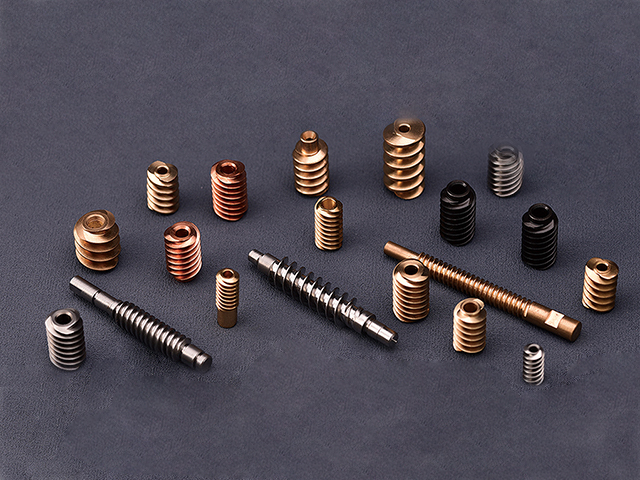
Auto parts-Axis, Worm delivers precision components engineered via CNC machining for seamless integration in industrial equipment. Custom parts provide durable, reliable machined metal parts tailored to exact specifications.
An axis and a worm work as a pair. The worm carries the thread; the axis carries the driven member, and together they turn rotation through a right angle with a high reduction in a compact envelope. That is why the pair appears in automotive adjustment and actuator mechanisms, and in industrial equipment such as gear reducers, valve and damper actuators, indexing units and machine-tool feed assemblies.
Both components are machined to your drawing, from bar stock, on CNC lathes and machining centres. Because our CNC machining services handle these machined metal parts as one job, the thread form, journal diameters, keyways, flats, steps and mounting features all follow the same drawing set for the worm and the axis, and the two parts arrive as a matched set instead of two unrelated purchases.
Sizes and finishes are fully custom. You choose the metal that suits the duty and the environment; we cut the dimensions, the profile and the surface your assembly needs and then hold those numbers across the whole order. As a CNC machining parts manufacturer working with automotive and industrial equipment builders, we are used to drawing sets that are still being revised, so tell us which dimensions decide whether the assembly runs and which ones can take a sensible general tolerance. The part is then made to that hierarchy.
| Item | Specification |
|---|---|
| Component range | CNC machined axis and worm components, produced to drawing |
| Production basis | Your 2D drawing or 3D model, including the tolerance and finish notes |
| Machining processes | CNC turning, milling, drilling, boring, grinding, wire cutting and EDM |
| Geometry | Shafts, worms, journals, bearing seats, keyways, flats, steps and thread profiles as drawn |
| Heat treatment | Hardening, case hardening, nitriding, induction hardening and stress relief |
| Surface finishes | Anodising, nickel plating, blackening, polishing, sandblasting and brushing |
| Inspection | Dimensional checks and thread gauges used during production |
| Customisation | Size, thread form, finish, marking and quantity set by your specification |
The two parts only work as well as their relationship. Centre distance, lead and backlash are decided by the geometry of the worm and the axis together, so two components each made neatly to their own drawing can still run badly if the housing positions them differently.
On the machining side we cut the thread profile your drawing calls for, whether that is a standard worm form or a proprietary profile you have developed in house, and we keep journals, bearing seats and locating shoulders concentric with the thread where the drawing shows that relationship. Holding those features to each other is what keeps the pair aligned on assembly and stops the load landing on the edge of the flank instead of across it.
Every set is a custom CNC machining job rather than a catalogue pick, so the details that decide how the drive runs, such as lead, flank finish and centre distance, can be built into the part instead of worked around at assembly.
Part of backlash belongs to the components and part of it belongs to the housing. If an assembly runs tight or loose, re-machining the next component to the same dimensions will not change it. Tell us the backlash you need at assembly, and send the housing drawing or the mating component with the order so the pair can be considered together rather than in isolation.
Worm drives also live or die on lubrication and running-in. Use the lubricant the equipment manufacturer specifies, keep the initial running load light, and check the contact pattern before the equipment goes into continuous duty.
| Option | Typical fit |
| Alloy steel, hardened after machining | Worm shafts and axes under continuous drive load, where surface hardness and a tough core both matter |
| Case-hardened alloy steel | Wear surfaces that need a hard skin over a shock-resistant core |
| Stainless steel | Assemblies exposed to moisture, washdown or outdoor conditions, where corrosion resistance comes first |
| Copper alloys and bronze | Wheel and bush parts running against a steel worm, where low friction matters more than strength |
| Aluminium alloys | Lighter shafts, housings and brackets, where low weight matters more than surface life |
| Titanium alloys | High-strength, low-weight components for demanding or corrosive environments |
| Engineering plastics and POM | Low-load, low-noise or non-magnetic parts, insulators and dampers |
| Ceramics | Wear surfaces and insulators where hardness and electrical isolation are needed |
| Hardening, case hardening, nitriding | Raise the surface wear resistance of steel worms and axes |
| Stress relief | Stabilises a part between rough and finish machining so the final dimensions hold |
| Anodising, nickel plating | Corrosion protection and a controlled appearance on aluminium and steel parts |
| Blackening, polishing, sandblasting, brushing | Surface condition and appearance for exposed parts and for assemblies that have to match visually |
Reproducing a worn component
Machines often outlast their paperwork. When the drawing for an axis or worm has been lost and the part itself has worn out, replacing the whole drive is rarely the answer a maintenance team wants, and it is usually not necessary. Send the worn component together with anything you still hold on it: an older drawing revision, the spare-parts list from the machine manual, the notes your fitters took before removal, and, where possible, the housing or the mating worm so the two can be considered as a pair. We measure the sample first, then send you the dimensions, material and heat treatment we propose, and only start custom CNC machining once you have approved that specification.
How much can be recovered from a used part depends on how it wore. Journals, keyways, steps, shoulder positions and overall lengths stay measurable even after long service, while thread flanks and a damaged spigot are harder to read. Where the flank has worn, we rebuild the form from the section of thread that is still intact and from the lead that remains, and we tell you honestly when a sample supports only an approximate profile rather than an accurate one. A component that has run with a seized or broken bearing is the most difficult of all, so send the most representative worn part you have rather than the worst one on the shelf.
A worm and its axis bed into each other in service, so fitting one new part against a used one rarely gives the contact pattern of a new set. If the mating component is also past its limit, replacing both together is usually the sounder route, and the second part costs little against another strip-down. Where the equipment has been superseded and the housing has changed as well, ask us about an upgraded pair built to the current interface instead of an exact copy of the original.
Storage and handling before assembly
Parts that arrive correct and then sit badly still cause fit problems, and those problems are usually remembered as a supplier issue. Keep the components in the protective film they are packed with until assembly, store them clear of damp air and of places where condensation forms overnight, and renew the film if they are held for months rather than weeks. Tell us at the ordering stage if the parts will wait a long time before fitting, so the protective packing can match that storage period.
Treat threads, journals and flanks as working surfaces. Keep them off bare metal shelving and out of contact with one another, and stand slender shafts upright or leave them in their packing rather than laying them across a bench where they can pick up a knock or a bend. Anodised and plated surfaces carry the corrosion protection, so wipe them rather than scrubbing with abrasive pads, and do not leave the parts standing in water-based coolant or cleaning fluid.
Check the delivery while everything is still clean: measure the features listed on the approved specification and look over the thread form and finish, so anything that needs raising is raised at goods-in rather than at the assembly bench. Before fitting, wipe the protective oil off with a lint-free cloth and lubricate with the grade the machine builder specifies, because a steel worm or axis left degreased and dry will start to mark from the first turn.
Keep the first hours of running light and check the contact pattern before the equipment goes into continuous duty, since backlash and contact position are easiest to correct early. If the pattern sits at one end of the flank or the pair runs hot, send us photographs and the running conditions before continuing; the cause is almost always alignment or lubrication rather than the parts themselves.
Suntontop is a precision machining factory based in Shenzhen, China, founded in 2014 and now 300 people strong, with more than ten years of hands-on processing practice. We run a sufficient number of CNC and other processing machines, so capacity can be adjusted flexibly to match order volumes, and every order is produced to your drawings under full-process quality control supported by more than 100 sets of inspection equipment. We support OEM and ODM custom manufacturing for machinery manufacturers and industrial distributors across Europe, the Americas, Southeast Asia and Central Asia, with on-time delivery and responsible after-sales support.
The running duty decides it more than anything else. In most worm drives a hardened steel worm runs against a copper-alloy or bronze wheel, stainless steel takes over where corrosion is the bigger risk, and aluminium alloys, titanium alloys, engineering plastics, POM and ceramics are machined here for lighter or more specialised parts. Give us the load, the environment and the running speed with the drawing, and we will propose the material and heat treatment and confirm the choice with you before production starts.
Yes. Sizes and finishes are fully custom, and so is the geometry between them: diameters, lengths, thread profiles, keyways, flats, steps and mounting features are all machined from your drawing or model. Send the drawing with the dimensions you consider critical, and we will produce precision machined parts to those numbers, from a small validation quantity up to a series order.
The method is fixed before the batch starts. The drawing revision, the material and the heat treatment are agreed, a first article is approved against the drawing, and production then follows that approved method under the eye of our quality engineers. Consistency across deliveries comes from repeating the same method, which is also why a part ordered later behaves like the first one. If your quality team needs certification or inspection documents for the order, ask your sales contact and they will confirm what we can issue.
We work on the assembly, not just on the part. That means early design validation against your drawing, prototype testing before a batch is committed, and assembly checks that show how the machined metal parts sit against their mating components. Reviewing fit at drawing stage usually removes clearance and interference problems before they cost you a build, and it shortens the time between approval and series production.
Both parts are machined from one drawing set, so lead, thread profile and journal alignment are set relative to each other rather than independently. Send the housing drawing or the mating component as well, because centre distance, and therefore backlash, is partly decided by the housing rather than by the parts alone. If your drawing or assembly notes specify a backlash target, tell us during drawing review and we will say what the custom CNC machining can hold before the order is confirmed.
Often, but it depends on what can still be measured. Send the worn part together with whatever dimensions you have, and the housing or mating component if possible, and we will confirm what can be reproduced and what has to be agreed before the work starts. Worn surfaces and damaged threads limit how much can be read from a sample, so send the most representative example you have rather than the worst.
Keep steel parts lightly oiled and out of damp air, and stop threads and machined faces knocking against each other in the crate, because the finish on a worm thread is part of how the drive runs rather than a cosmetic detail. Keep each order together and fit the parts as a set rather than pairing a worm from one delivery with an axis from another.
Yes, within the limits of the base material. Anodising, nickel plating, blackening, polishing, sandblasting and brushing are all carried out here, and appearance can be matched against a sample you send, because anodised and plated colours shift slightly with alloy and surface preparation. Where the part sits hidden inside the assembly, a functional finish such as hardening or plating is usually the better choice than a cosmetic one.